We Couldn't Buy the Board We Needed, So We Designed Our Own PCB with Claude Code
We needed a USB-C Power Delivery breakout for a hardware project and the board that fits can't be bought right now. So we designed and manufactured our own with KiCad and Claude Code. Here's the full build, including the mistakes.

Stabilise
There is a moment in every hardware project that never stops being magic: the courier hands you a box, and inside is a physical object that was an idea a few weeks ago. This week that object was our first ever circuit board, and it exists because the board we needed cannot be bought right now.
This is also the first post in Stabilise Labs, where we write up the experiments and side-quests behind our main work. Expect fewer polished case studies and more honest build logs, mistakes included.
Why an IT company is designing circuit boards
We are building a piece of hardware for BlankState, our ITAD SaaS platform: an automatic DFU device. The idea is simple to describe and fiddly to build. Plug a single USB-C cable into a Mac or iOS device's DFU port, and the device on the other end puts the machine into DFU mode.
DFU matters in IT asset disposition because it is the lowest-level restore state Apple hardware has. If you are erasing and reprovisioning hundreds of Apple silicon Macs, getting each one into DFU is the gate every machine passes through, and Apple's manual route involves a second Mac, Apple Configurator and a key-combination dance with precise timing.
BlankState already removes most of that pain. DFU Prep is built into the app: connect the target Mac to the host machine running BlankState, click Place in DFU Mode, and the machine reboots straight into DFU, ready for batch wiping. One click instead of a finger ritual, repeated for as many Macs as you can hand over the desk.
BlankState's DFU Prep placing a connected MacBook Air into DFU mode with one click.
The device we are prototyping takes the idea further: the same capability shrunk into a dedicated piece of hardware, so entering DFU needs nothing more than plugging in a cable. The mechanism that makes this possible is publicly documented: Apple devices listen for vendor defined messages on the USB-C Power Delivery channel, and the right message sequence can reboot a machine into DFU over the cable alone. To prototype that, our microcontroller needs a USB Power Delivery PHY, which is the chip that speaks the PD protocol on the wire. The standard choice is the FUSB302B from onsemi.
There is a well-known FUSB302B breakout board that the community has relied on for years. At the time of writing, you cannot buy it. So we designed our own.
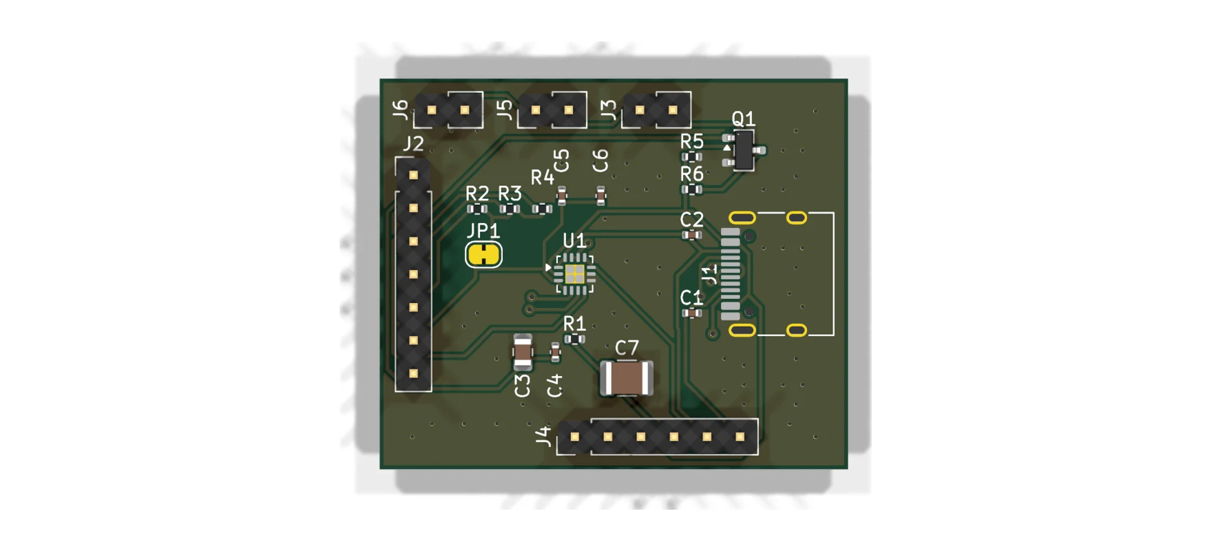
What we built
The board breaks out the FUSB302B and stays deliberately unopinionated about everything else. If you have ever wanted a project to ask a USB-C charger for 9, 15 or 20 volts, or to be the thing doing the charging, this chip handles the messy analogue side: CC line detection, attach and orientation sensing, and transmitting and receiving the PD protocol's messages. Your microcontroller does the negotiation logic over I2C.
The design choices:
- VBUS goes straight to the connector. No load switch on board, because the right switch depends entirely on your application. Bring your own. Rated for the full 20 V PD range.
- Active VBUS discharge on board. The USB-C spec wants VBUS below 0.8 V within 650 ms of detach. A passive bleed alone is either too slow or too wasteful, so there is a MOSFET discharge path you control from a header pin, plus a 47 k bleed.
- I2C up to 1 MHz, with on-board pull-ups you can disconnect by cutting a solder jumper. PD timing is strict enough that slower MCUs genuinely benefit from the faster bus.
- Everything broken out: CC1/CC2 for probing, SBU1/SBU2, USB 2.0 data, VCONN for powering cable eMarkers, and three paralleled VBUS/GND pad pairs for higher-current use.
All of it on a 36 x 30 mm two-layer board with standard 2.54 mm headers. And because we could not resist, the Settle mark went on the back silkscreen.
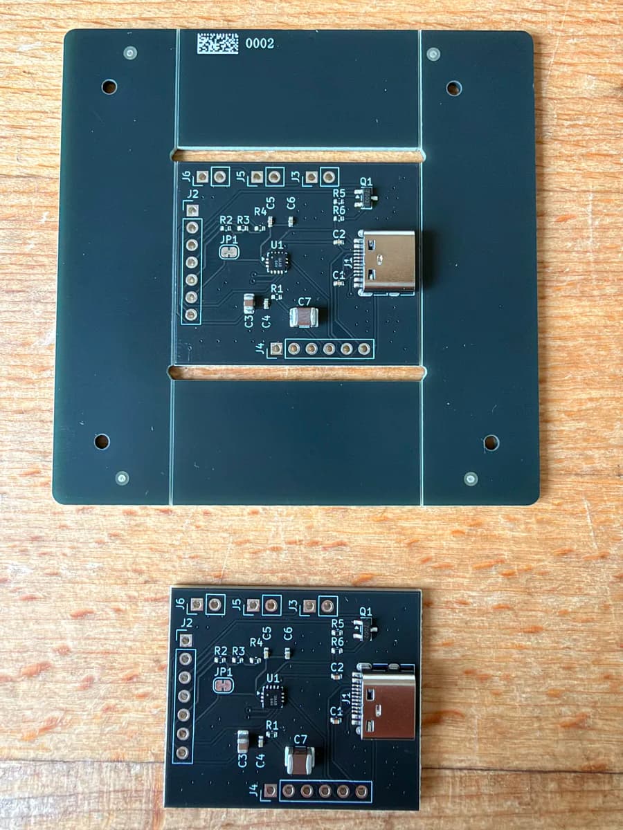
Rev 1 back from the fab: front and back. If you are going to make hardware, sign it.
The unusual part: nobody drew this board
Neither the schematic nor the layout was drawn by hand in an editor. The whole design was built programmatically in Claude Code. KiCad stores its files as plain s-expressions, which makes them surprisingly tractable for an AI agent: it writes a Python script that generates or edits the design, renders the board to an image, looks at the result, and fixes what is wrong. Then it runs the design rule checker and goes again.
The script names left behind in the project folder tell the honest version of the story: route_pcb.py, then fix_routes.py, then fix_gnd_islands.py, finish_dm2.py, cleanup_vias.py. Routing a board this way took real iteration, exactly like it does for a human, and the agent did not get it right first try. What it did do was keep the entire design process scripted, reviewable and repeatable, with a human steering and reviewing every step. AI agent as junior PCB designer, human as design authority.
Rev 1 confessions
No first revision is perfect, and being honest about the warts is half the point of writing this up.
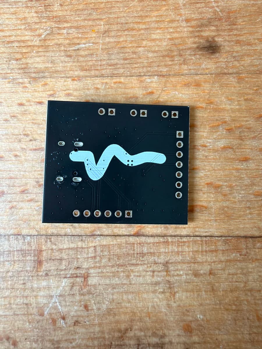
1. There are no signal names on the silkscreen. The pads carry only reference designators. Somewhere between schematic generation and tape-out, nobody, human or AI, put signal labels on the silk. The fix for now is a pinout diagram generated directly from the design files, so the labels are guaranteed to match the copper. Rev 2 gets proper silkscreen.
 The pinout diagram, generated straight from the KiCad files rather than drawn by hand.
2. One resistor limits sustained 20 V use. R1, a 4.7 k bleed sitting permanently across VBUS, dissipates 85 mW at 20 V. That is past the comfort zone of an 0402 package and wastes a constant 4 mA. For long-term operation above roughly 12 V, desolder it; the active discharge path and the 47 k bleed remain. Rev 2 changes the value.
Where it stands
The boards arrived this week and visually match the design files. We have not powered one up yet, deliberately. Bring-up happens on the breadboard as the auto DFU prototype comes together, and the first milestone is the classic "it's alive" moment: reading the chip's device ID back over I2C.
If testing goes well, rev 2 fixes the silkscreen and R1, and we may make boards available for others who are stuck without a FUSB302B breakout to buy. The DFU device itself will find its way into BlankState once it has earned it.
For a company that spends its days in MDM consoles and security baselines, there is something grounding about a project where the failure modes are measured in milliwatts. More from the Labs soon.